Simatic PCS 7 is the DCS system of Siemens

Picture 1: Simatic PCS 7 structure
The first layer is OS – Operation Station, this is the core of PCS, with this layer the operators can control, monitor and see the warning, alarming of the operation. They also can use the other resource on OS to do the analysis to get a better operation such as: data, trends, etc
In the second layer, we have 3 parts as parallel.
First part is data server, this server has the function is transfering data between OS and controllers. For example, data is analog value from temperature sensor transfer from controller to data server and from data server to SCADA in OS to let operator know about temperature on site
The second example is when operator press the button on SCADA to open the valve, this signal will be sent to data server and come to PLC, and PLC will export current/voltage to control the valve open on site.
The second part in this layer is Engineering Station (we call ES), for automation engineer this is the workplace, it can be a server or a computer. With ES, automation engineer can do:
- Configure the controller, IO, field device, PC station, servers
- Create project to program logic for PLC, design SCADA, set up network, configure the communication between PLC with other device
- Download these project to PLC, OS, server
- Some administration tasks.
The third part is historian server, this can be a server or a computer has the function to store historical data that can be used for trends or other tool to improve for operation
The next layer is controllers, they has the function to get data from IO that connect to field device or from equipment via industrial connection such as Ethernet, Profibus. After getting data, controller will transfer to data server to show on OS or store in historian server or serve for programming, troubleshooting in ES. Parallel, controller also get the command from OS via data server to control the device or directly from ES to support for troubleshooting or improvement.
The next layer is input output module, this is the connection between PLC and field device.
And at the bottom is field device such as: sensor, valve, contactor, encoder, etc
1 more thing is about communication between OS, server, ES, PLC, IO is Ethernet (another name is Profinet), for field device PCS 7 support with fieldbus protocol.
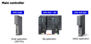
Picture 2: Simatic PCS 7 main controller
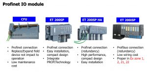
Picture 3: Simatic PCS 7 Profinet IO modules
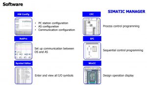
Picture 4: Simatic PCS 7 software
All of these software, Siemens already integrate all-in-1 with Simatic Manager
Watch more detail in video: Simatic PCS 7 Overview