
1. What are machine vision systems?

Machine vision systems are generated by integrated components include: vision camera/sensor, computer hardware, and software algorithms that offer operational guidance by processing and analyzing the images captured from their workspace. The data acquired from the vision system are used to control and automate a process or inspect a product or material.
2. Components of machine vision systems
Machine vision systems are typically included of five key components. These components are common and may be seen in other systems.
- The key component – the vision camera or sensor, I will combine camera and sensor into 1 type of component because they have same function is detect differences, a vision camera mission is capturing the image of product that is material for its processor and software to analyze is it a defect or good
- Second thing very important is lighting, the camera cannot capture a high quality image without lighting, it’s not simple just illuminate for product, for each of distinct feature on product we need to set up a different position and light technique.
- Third thing is lens: The lens collects light scattered of an object and reconstructs an image of that object on the camera sensor
- 4th thing is processing unit and visual display, it can be a computer with software that develop from camera manufacturer to show and set up tools for detection, so we can see every product through and result of detection good or bad, some brand also has special HMI for their camera, so we can link directly from that HMI to camera and see the image of product and fault on that HMI
- 5th thing is communication system include: camera controller please take note that some camera model/brand will not have controller, PLC, and rejection mechanism.
2.1. Vision/Image sensor

The image sensor captured by the lens into a digital image. Technology to translate photons into electrical signals:
- CCD
- CMOS
The output of image sensors is a digital image composed of pixels that shows the presence of light in the areas that the lens has observed.
Resolution is the number of pixels produced by the sensor in the digital image. Sensors with a higher resolution produce higher quality images, meaning more details can be observed in the object being inspected, and more accurate measurements can be achieved.
Sensitivity is minimum amount of light required to detect a output change in the image..

Resolution and sensitivity are inversely related to each other; an increased resolution will decrease the sensitivity.
2.2. Lighting
- Responsible for illuminating the object and highlighting its distinct features to be viewed by the camera.
- Parameters: distance of the light source from the camera and object, angle, intensity, brightness, shape, size, and color of lighting must be optimized to highlight the features being inspected.
- Can be provided by LED, quartz halogen, fluorescent, and xenon strobe light sources. It can be directional or diffusive.
- 6 techniques

Lighting – Bright Field vs Dark Field

|
|
Lighting – Back lighting

- Illuminates object from behind à creates contrast as dark field appear against a bright background
- Used to detect holes, gaps, cracks, bubbles, and scratches on clear parts
Lighting – Diffuse Dome vs Flat vs Axial

Illumination with a larger “solid angle”, is that light is sourced from a large area and is incident on the object surface from multiple angles
- Dome Diffuse Light is very effective on specular, curved, and topographic surfaces
- Axial Diffuse is effective for specular, flat, and angled surfaces of varying heights
- Flat Diffuse the similar performance characteristics with classic dome, effective for inspecting highly specular, and curved objects, but at close working distances
2.3. Lense
The lens captures the image and relays it to the image sensor inside the camera in the form of light. The lens of a machine vision camera can be an interchangeable lens (C-mount or CS-mount) or a fixed lens.
Lenses are characterized by the following properties, which describes the image quality they can capture:
- Field of view refers to how much area the image sensor views; lenses with higher focal length have a reduced field of view.

Photo 7: Field of view - Depth of field refers to the ability to maintain acceptable image quality without refocusing if the object is moved farther from the plane of best focus. It also influences the object’s range of acceptable motion.

- Aperture is the opening of the lens through which light passes to enter the camera. It controls the amount of light entering the lens. It is inversely related to the depth of field.

2.4. Processing unit and visual display
The vision processing unit of a machine vision system uses algorithms to analyze the digital image produced by the sensor. Vision processing involves a series of steps, performed externally (by a computer) or internally (for stand-alone machine vision systems). First, the digital image is extracted from the image sensor and is relayed to the computer. Next, the digital image is prepared for analysis by making the necessary features on the image stand out. The image is then analyzed to locate the specific features needed to be observed and measured. Once observations and measurements of the feature are completed, they are compared to the defined and pre-programmed specifications and criteria. Finally, the decision is made, and the results are communicated.

About visual display, for each of vision camera brand, we will have a software to visualize captured image and result of inspection, that software we can do all the thing for setting up the vision camera such as:
- Set reference image
- Define right location of object or product
- Add tool to inspect
- Set up for PLC communication

2.5. Communication system to controller PLC and rejection mechanism
For communication between vision camera and PLC, nowadays, almost vision cameras have Ethernet communication protocol and gate, so we can connect directly to PLC, if I need more station for HMI or PC, we can use a hub/switch
If camera doesn’t have a Ethernet connector, it can connect to PLC via I/O
And for rejection mechanism, it is belong to PLC side, PLC takes inspection result from camera and will have generate a command for rejection mechanism, it can be a cylinder to kick out defected product.
3. Types of machine vision systems

- A line-scan camera captures digital images one line at a time, it can inspect multiple objects in a single line. They are ideal in high-speed conveying systems and continuous processes. They are suitable in continuous webs of materials, such as paper, metal, and textiles, large parts, and cylinders.
- Area scan cameras use rectangular-shaped image sensors used to capture images in a single frame. Area scan cameras can perform almost all common industrial tasks and are easier to set up and align. Unlike line scan cameras, it is preferred in inspecting stationary objects.
- 3D scan cameras can perform inspections at X, Y, and Z planes and calculate the object’s position and orientation in space. They utilize single or multiple cameras and displacement sensors. In a single-camera setup, the camera must be moved to generate a heightmap that resulted from the displacement of lasers’ location on the object. The height of the object and its surface planarity can be calculated using a calibrated offset laser. In a multi-camera setup, laser triangulation is deployed to generate a digitized model of the object’s shape and location. 3D scan cameras are ideal for inspecting 3D-formed parts and robotic guidance applications. This type of machine vision camera can tolerate slight environmental disruptions (e.g., light, contrast, and color variations) while providing precise information. Hence, they are widely used in metrology, factory automation, and defect analysis of parts.
| Line Scan Camera | Area Scan Camera | 3D Scan Camera |
| Stationary objects |
|
4. Functions performed by machine vision systems
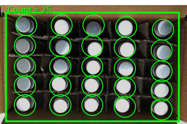
Presence Inspection
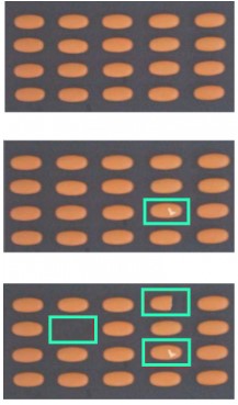
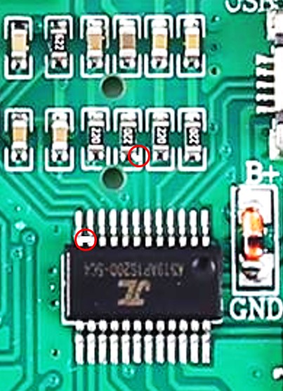
Presence inspection is the process of confirming the quantity and presence or absence of parts. It is one of the basic operations performed by machine vision systems and the most widely performed tasks in most industries. Practical applications of presence inspection include counting of countable products (e.g., bottles, screws) and checking the presence of labels on food packaging, electronic components on PCBs, adhesive application, and screws/washers in fastened parts.

Practical Positioning
Positioning is the process of comparing the location and orientation of the part to a specified spatial tolerance. The location and orientation of the part in 2D or 3D space are communicated to a robot or a machine element for it to align or place the target in its proper position or orientation. Machine vision positioning systems offer more accuracy and speed than manual inspection, alignment, and positioning. Practical positioning applications include robotic pick and place parts on and off the conveyor belt, positioning of glass substrates, checking of barcode and label alignment, checking of IC placement in PCB, and arrangement of parts packed in a pallet.

Identification
Machine vision identification scans and reads barcodes, 2D codes, direct part marks, and characters printed on parts, labels, and packages. These markings contain product name, manufacturer, date code, lot number, and expiration date. Identification is useful in improving the traceability of parts, inventory control, and verification system of products. Identification is accomplished by either an optical character recognition (OCR) or an optical character verification (OCV) system. In OCR systems, the machine vision reads the printed alphanumeric characters on the target without prior knowledge of the characters to look for. In OCV systems, the machine vision verifies the presence of the character strings.

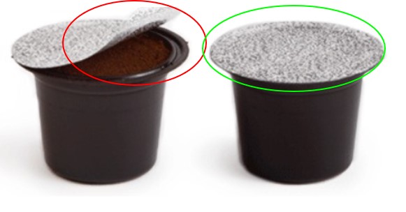
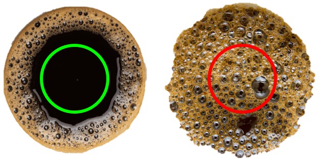
Flaw Detection
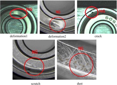
Flaw detection is one of the most fundamental quality control tasks in manufacturing industries and the most utilized function of machine vision systems. In flaw detection, the machine vision searches for defects such as cracks, scratches, blemishes, gaps, contaminants, discoloration, and other irregularities present on the part’s surface, which can affect the product functionality and reliability. Next, the presence of these defects is monitored. The machine vision system can categorize the defects by type, color, texture, and size and sort out the defective parts failing the criteria. Machine vision systems can quickly and effectively detect small and microscopic flaws, which can be invisible to the human eye; these systems can work or operate for long periods of time, unlike human inspectors.

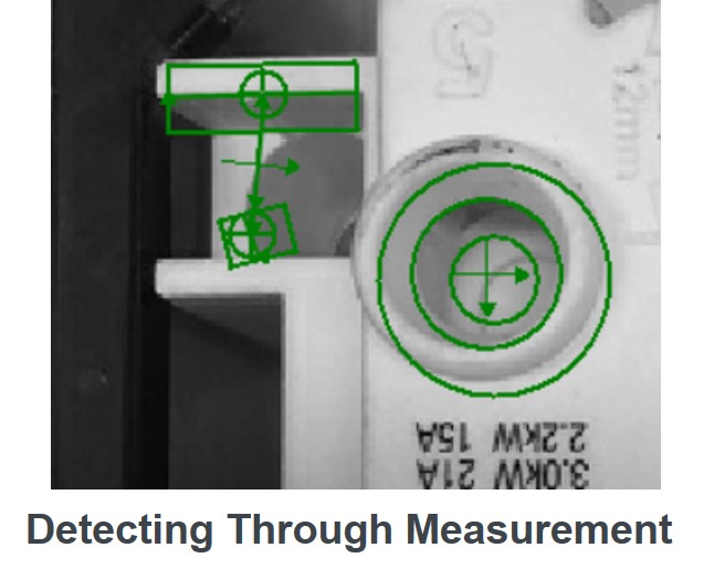
Detecting Through Measurement
Measurement is the checking of dimensional accuracy and geometric tolerances of parts. The machine vision system calculates the distances between two or more points and the location of the targeted features on the object to determine whether the measurement is within specifications. The lighting and optical system of the machine vision system must be optimized in order to obtain highly accuracy and repeatable measurements.
The measurement function of machine vision systems can measure features as small as 25.4 microns. It typically comes together with flaw detection to measure the irregularities detected in parts. It is also used in calculating the volume of parts.
5. Applications of machine vision systems

More detail explanation: https://www.youtube.com/watch?v=YNhT9_LpyGM
FlexBitAutomation.com

