Welcome to the Rockwell Automation series on device control. In this technical writing, we will discuss how to program a 2-way valve using a PLC ControlLogix 1756-L83E. The process will be explained step by step, covering topics such as creating a new user-defined datatype, logic instruction for datatype members, and programming control for the 2-way valve.
Purpose: The purpose of this technical writing is to demonstrate the programming process for controlling a 2-way valve using a PLC ControlLogix 1756-L83E. By following these instructions, you will understand how to efficiently create tags for valves using a user-defined datatype.
Benefits of User-Defined Datatype: The creation of a user-defined datatype for the 2-way valve offers several benefits, including:
- Time-saving: By using a user-defined datatype, the process of creating tags for valves is significantly expedited. Creating tags for ten valves can now be completed in approximately 10 minutes.
- Consistency: The use of a uniform datatype ensures consistency in tagging and programming across multiple valves.
- Easy maintenance: With a user-defined datatype, any modifications to the 2-way valve’s properties can be made in a centralized location, improving maintainability.
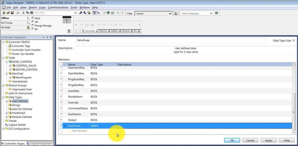
3. Creating a User-Defined Datatype: To begin, we need to create a new user-defined datatype called “Valve2Way.” This datatype will streamline the process of creating tags for multiple valves in our system.
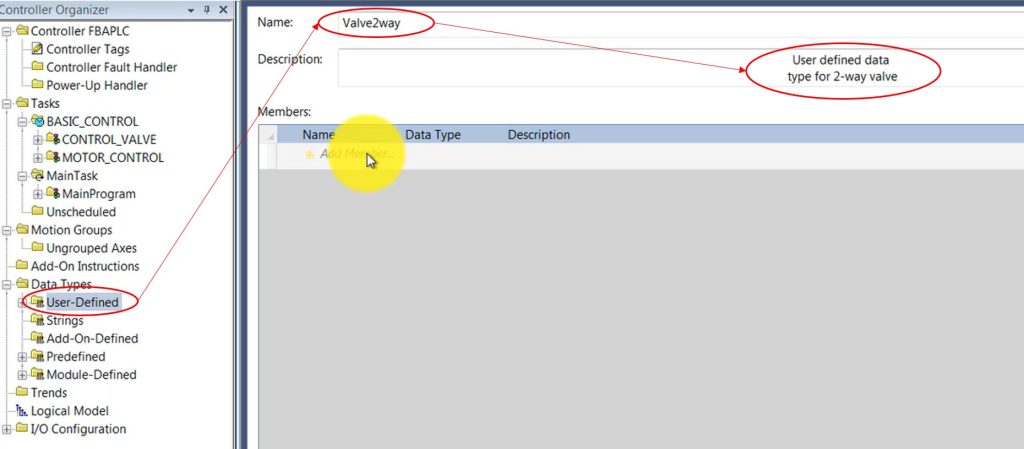
- Right-click on the user-defined folder and select “New Datatype.”
- Name the datatype “Valve2Way.”
- Provide the description “User-defined datatype for 2-way valves.”
4. Member Grouping: To organize the user-defined datatype efficiently, we will separate the members into seven groups:
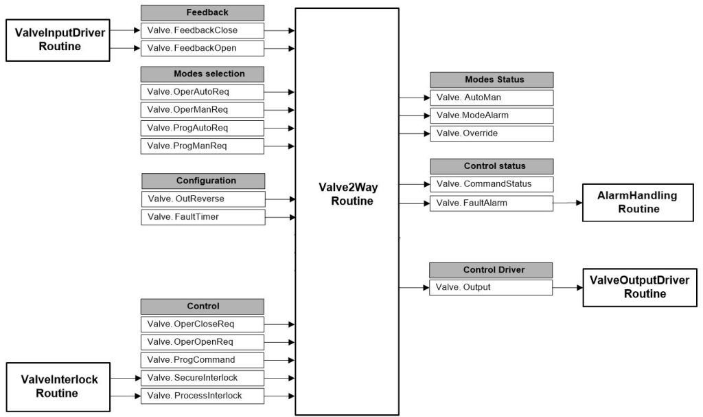
a. Feedback: This group will include properties related to receiving feedback from the valve.
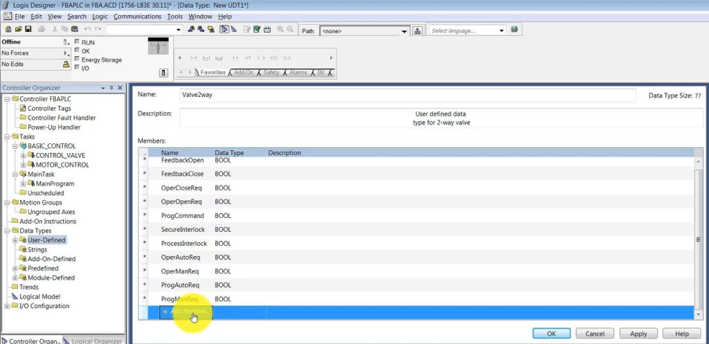
- FeedbackClose data type is BOOL, this is feedback from valve is close.
- FeedbackOpen data type is BOOL, this is feedback from valve is open.
b. Control: The control group will contain properties essential for controlling the valve.
- OperCloseReq means Operator state CLOSE request, data type is BOOL. Set by the operator interface (SCADA) to place the valve in the Close state when the valve is in Manual control.
- OperOpenReq means Operator OPEN request, data type is BOOL. Set by the operator interface (SCADA) to place the valve in the Open state when the valve is in Manual control.
- ProgCommand means Program Command, data type is BOOL. Used to determine CommandStatus when the valve is in Auto control and set by the user program. When set, the valve is commanded to the Open state; when cleared, the valve is commanded to the Close state
- Secure Interlock. It is Used to override request in case of safety issue. It will open/close the valve when have any safety issue, for example when steam pressure is over high alarm limit then close the valve supply steam.
- Process Interlock. It is also interlock but related to process condition to prevent the wrong operation.
c. Modes Selection: Here, we will define properties for selecting different modes of operation.
- OperAutoReq means Operator Auto request. Set by the operator interface (SCADA) to request Auto control.
- OperManReq means Operator Manual request. Set by the operator interface (SCADA) to request Manual control.
- ProgAutoReq means Program Auto request . Set by the user program to request Auto control. Holding this set and ProgManReq cleared locks the instruction into Auto control
- ProgManReq means Program Manual request. Set by the user program to request Manual control. Holding this set locks the instruction into Manual control.
d. Modes Status: This group will include properties for monitoring the current status of different modes.
- AutoMan, Set when in Auto control. Cleared when in Manual control.
- Mode alarm, Mode alarm output. Set if the valve is in Manual control and a program command changes to a state which is different from the state currently commanded by the operator. This alarm is intended as a reminder that a valve was left in Manual control
- Override mode, Set by the SecureInterlock OFF to request the valve to enter Override mode and OverrideState.
e. Control Status: Properties related to the status of the control system will be included in this group.
- Commandstatus, Command status output. Set when the valve is being commanded to Open and cleared when the valve is being commanded to Close
- Faultalarm, Fault alarm output. Set if the valve was commanded to a new state and the FaultTimer has expired without the feedbacks indicating that the new state has actually been reached. Also set if, after reaching a commanded state, the feedbacks suddenly indicate that the valve is no longer in the commanded state. The Fault Alarm is NOT latched and is reset as soon as the feedbacks indicate the right state, thus the operator do not need to unlatch the alarm
f. Configuration: The configuration group will contain properties for setting up the valve’s parameters.
- OutReverse: Reverse default Output state. The default state of Output is cleared when commanded to state Close, and set when commanded to state Open. When OutReverse is set, Output is set when commanded to state Close, and cleared when commanded to state Open.
- Fault timer that Is the timer will count from valve receive the program command, if in the preset time, the valve on site do not move follow the command, the fault alarm will be set and alarm on SCADA or HMI. That tag I name is FaultTimer and data type is timer. Set FaultTimer.PRE = 0 to disable the fault timer
g. Control Driver: This group will consist of properties specific to the control driver.
- Output: The output of the instruction, which is commanding the valve
Conclusion: In this technical writing, we have explored the process of programming a 2-way valve with a PLC ControlLogix 1756-L83E. By creating a user-defined datatype, we can streamline the tag creation process, saving time and improving consistency. Following the steps outlined above will enable you to efficiently control and configure valves in your system.
Detail explanation in video:
https://www.youtube.com/watch?v=wa6EWwDof6w&list=PLFZXAg2fI5PSAKMStLj8wH2_hHdJlYpBW&index=3

